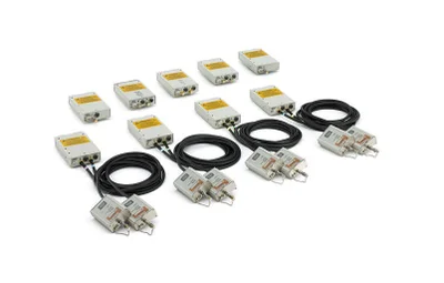
Quick quote: Tektronix 80E09B
Tektronix 80E09B
Model
80E09BProduct Family
Oscilloscopes & Logic AnalyzersManufacturer
TektronixConfigured models contain the following attributes:
Oscilloscopes & Logic AnalyzersSampling Oscilloscopes50GHz <= 85GHzLet us help you with your exact configuration
Please use 'Get Quick Quote' and we’ll contact you and quote for your exact need.
You can also get in touch, if you prefer, and our experts will be able to guide you with the right application and procurement solution for this product.
Key Specs
| Attribute | Value |
|---|---|
| High Frequency (range) | 50GHz <= 85GHz |
Product Overview
The DSA8300 Series Sampling Oscilloscope, when configured with one or more electrical sampling modules, provides complete test solutions for multi-channel, high-bandwidth electrical applications. This highly configurable solution is well suited for debugging, characterizing and analyzing components, modules and systems with signaling rates at 10, 40 and even 100 Gb/s.
The 80E00 family of electrical sampling modules provide a wide variety of capabilities, allowing the user to configure a test solution specifically adapted to their application.
| Key Features |
| Independent sampler deskew ensures easy fixture and probe de-embedding |
| Dual channel (except 80E11X1) |
| Precision Microwave Connectors (3.5 mm, 2.92 mm, 2.4 mm, and 1.85 mm) |
| Probe support |
| Key Performance Specifications |
| Up to 70 GHz bandwidth and 5 ps measured rise time (10-90%) |
| Lowest noise for analysis: 450 μVRMS at 60 GHz, 300 μVRMS at 30 GHz |
| 15 ps reflected true differential fully integrated TDR rise time (12 ps incident) and feature resolution below 1 mm (TDR modules) |
| Efficient, accurate, easy to use, and cost-effective S-parameters up to 50 GHz |
Remote samplers¹ enable location of sampler near DUT and ensure best signal fidelity note: ¹ Integrated on 80E07B - 80E10B and optional on 80E03, 80E04, 80E11 and 80E11X1. |
| Applications |
| Impedance characterization and S-parameter measurements for serial data applications |
| Advanced jitter, noise, and BER analysis |
| Channel and eye-diagram simulation and measurement-based spice modeling |
80E10B, 80E08B, and 80E04: High-performance TDR/T measurements Impedance profile, inductance, capacitance, and S-parameters Transmission line quality, impedance, and crosstalk True differential, common mode, and single-ended measurements Efficient fault isolation |
80E11, 80E11X1, 80E09B, 80E07B: High-frequency, low-noise signal acquisition Fast rise time measurements Jitter analysis and waveform analysis |
80E03, 80E03-NV: Device characterization, transmission quality, waveform parameters Low signal measurements |
| Specifications | |||||
| Electrical Sampling Modules | |||||
| Model Overview | |||||
| Module | Application | Bandwidth¹ | Channels | Input impedance | Input connector |
80E11 80E11X1 | High-frequency Low-noise Signal acquisition and jitter characterization | 70/60/(40) GHz² | 2/1 | 50 ±1.0 Ω | 1.85 mm female |
| 80E10B | True differential TDR S-parameters Fault isolation | 50/40/(30) GHz² | 2 | 50 ±1.0 Ω | 1.85 mm female |
| 80E09B | High-frequency Low-noise Signal acquisition and jitter characterization | 60/40/(30) GHz² | 2 | 50 ±1.0 Ω | 1.85 mm female |
| 80E08B | True differential TDR and S-parameters | 30/(20) GHz² | 2 | 50 ±1.0 Ω | 2.92 mm female |
| 80E07B | Optimal noise/performance trade-off for jitter characterization | 30/(20) GHz² | 2 | 50 ±1.0 Ω | 2.92 mm female |
| 80E04 | TDR impedance and crosstalk characterization | 20 GHz³ | 2 | 50 ±0.5 Ω | 3.5 mm female |
80E03 80E03-NV | Device characterization | 20 GHz⁴ | 2 | 50 ±0.5 Ω | 3.5 mm female |
Notes:
¹ Normal text is warranted values. Values in parenthesis are typical (unwarranted) value to which the instrument will typically perform.
² User selectable.
³ Calculated from 0.35 bandwidth rise time product.
⁴ The 80E03 bandwidth is calculated from 0.35 bandwidth rise time product. The 80E03-NV bandwidth is directly verified.
| Specifications | |
| Electrical Sampling Modules | |
| Model Overview | |
| Models | Description |
| 80E11 | Dual channel, 70+ GHz sampling module |
| 80E11X1 | Single channel, 70+ GHz sampling module |
| 80E10B | Dual-channel, 50 GHz true differential TDR sampling module with remote samplers |
| 80E09B | Dual-channel, 60 GHz sampling module |
| 80E08B | Dual-channel, 30 GHz true differential TDR sampling module with remote samplers |
| 80E07B | Dual-channel, 30 GHz sampling module |
| 80E04 | Dual-channel, 20 GHz true differential TDR sampling module |
| 80E03/80E03-NV | Dual-channel, 20 GHz sampling module ¹ |
| Instrument Options | |
| 80E04 Opt. 09 | Include two 80A09 EOS/ESD Protection Devices with the 80E04 module |
| Recommended Accessories | |
| 80E04UP Opt. 09 | 80E04 Upgrade kit; That provides two 80A09 EOS/ESD Protection Devices in a case that can hold an 80E04 module |
| 015-1001-xx | 2X attenuator (SMA Male-to-Female) |
| 015-1002-xx | 5X attenuator (SMA Male-to-Female) |
| 011-0157-xx | Adapter; (2.4 mm male to 2.92 mm female – can also be used as 1.85 mm male to 2.92 mm female) |
| P8018 | 20 GHz single-ended TDR probe. 80A02 module (below) recommended for static |
| P80318 | 18 GHz differential TDR probe. 80A02 module (below) recommended for static protection of each channel of the sampling or TDR module |
| 80A09 | 26 GHz ESD Protection Accessory |
| 80A02 | EOS/ESD isolation module (1 channel). P8018 or P80318 TDR probe (above) recommended |
| 80X01 | One-meter sampling module extender cable (for 80E11, 80E11X1, 80E04, 80E03, 80E03-NV) |
| 80X02 | Two-meter sampling module extender cable (for 80E11, 80E11X1, 80E04, 80E03, 80E03-NV) |
Note:
¹ For the 80E03-NV, bandwidth is directly verified and the Calibration Certification Report includes test data on the module's bandwidth test results.
Resources
File resources
Can't find what you are looking for?
Get in touch


