You are browsing the TW site. Would you like to be redirected to another country or region to see content and products specific to your location?
US
配置型號包含以下特性:
RF & Microwave Network AnalyzersEMC / EMI / RFI Analyzers100MHz <= 1GHz1kHz <= 100kHz| BENEFITS | |
| CURRENT PROBES | Current probes required by various EMI specifications (such as MIL-STD-461/2) are toroidal transformers designed to measure RF currents on active power lines or other conductors. |
| APPLICATION | A current probe is used as a “pick-up” device for measuring RF current in single conductors or cable bundles when connected to the 50 Ω input of a radio frequency interference measuring receiver or spectrum analyzer. |
| DESCRIPTION | Direct connection to the conductor carrying EMI current is not necessary, since the probe may be opened for insertion of the conductor into the window of the toroid and then closed again to form a toroidal transformer with the conductor acting as a one-turn primary. A correction factor graph is provided to convert measured µV to EMI µAs. When the EMI current is measured in dB above 1 µV as indicated on a conventional EMI meter, the correction factor will convert the measurement to dB above 1 µA. The correction factor is the inverse of the transfer impedance, Zt. Each probe is shipped with a graph of the correction factor versus frequency, keyed to the serial number on the probe. |
| BENEFITS | |
| INJECTION PROBES | Specifications require the injection of large high frequency currents into cable bundles and individual wires, using inserted secondary toroidal transformers placed around the conductors being tested. |
| APPLICATION | High power RF amplifiers with 50 Ω output impedance are used to deliver voltage to the injection probe. The wire or cable through the window of the probe acts as a secondary of the toroidal transformers. This test method is intended to be used instead of earlier methods, such as CS-01, CS-02, and RS-02 of MIL-STD-461. |
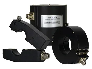
| DESCRIPTION | Bulk current injection probes are available in two styles: 1. Fixed window style where the wire(s) under test must be passed through the window. 2. A split toroidal design where the probe can be opened up and clamped over the wire(s) under test. Each probe is calibrated for insertion loss and transfer impedance in a test fixture designed for the particular window size. This fixture provides a signal path with a low Voltage Standing Wave Ratio (VSWR). A typical fixture is Solar Type 9125-1, used for probes with 32 to 44 mm diameter windows. |
| SPECIFICATIONS | |||||||
| Clamp on Current Probes Overview | |||||||
| Type Number | Window Diameter | Nominal ZTΩ | DC to 60 Hz | Maximum PRI. (pl) current, A 400 Hz | Maximum PRI. (pl) current, A RF (CW) | Maximum PRI. (pl) current, A Pulse | Frequency Range |
| 9124-1N | 1.25" (32.0 mm) | 0.001 | 200 | 70 | 50 | 5000 | 1 kHz - 200 MHz |
| 9205-1 | 1.25" (32.0 mm) | 0.33 | 800 | 800 | 50 | 100 | 20 Hz - 8 MHz |
| 9118-1 | 1.25" (32.0 mm) | 0.10 | 350 | 150 | 22 | 500 | 500 Hz - 200 MHz |
| 9134-1 | 1.25" (32.0 mm) | 0.70 | 500 | 400 | 5 | 100 | 20 Hz - 100 MHz |
| 6741-1 | 1.25" (32.0 mm) | 0.70 | 350 | 225 | 5 | 100 | 10 kHz - 100 MHz |
| 9207-1 | 1.25" (32.0 mm) | 1.0 | 800 | 450 | 4.2 | 100 | 20 Hz - 150 MHz |
| 9209-1 | 1.25" (32.0 mm) | 1.0 | 800 | 800 | 100 | 200 | 20 Hz - 30 MHz |
| 9145-1 | 1.25" (32.0 mm) | 5 | 350 | 350 | 42 | 100 | 10 kHz - 152 MHz |
| 9123-1N | 1.25" (32.0 mm) | 1-5 | 200 | 200 | 40 | 60 | 10 kHz - 500 MHz |
| 9214-1 | 1.25" (32.0 mm) | 5 | 600 | 600 | 21 | 200 | 20 Hz - 150 MHz |
| 9215-1N | 1.25" (32.0 mm) | 1-5 | 400 | 350 | 40 | 100 | 20 Hz - 500 MHz |
| 9231-1 | 1.25" (32.0 mm) | 0.010 | 300 | 200 | 7 | 3000 | 1 kHz - 200 MHz |
| 9219-1N | 1.25" (32.0 mm) | 0.025 | 400 | 300 | 150 | 200 | 20 Hz - 20 MHz |
| 9250-1N | 1.25" (32.0 mm) | 0.10 | 200 | 200 | 10 | 200 | 10 kHz - 450 MHz |
| 9257-1N | 2.62" (67.0 mm) | 4 | 500 | 500 | 200 | 200 | 20 Hz - 30 MHz |
| 9258-1N | 2.62" (67.0 mm) | 5 | 500 | 500 | 100 | 200 | 20 Hz - 100 MHz |
| 9261-1N | 2.62" (67.0 mm) | 2 | 500 | 500 | 2.6 | 100 | 20 Hz - 200 MHz |
| 9263-1N | 2.62" (67.0 mm) | 0.03 | 500 | 500 | 80 | 200 | 20 Hz - 100 MHz |
| 9301-1N | 2.62" (67.0 mm) | 8 | 350 | 350 | 60 | 200 | 20 Hz - 500 MHz |
| 9303-1N | 2.62" (67.0 mm) | 0.001 | 500 | 200 | 100 | 5000 | 20 Hz - 100 MHz |
| 9305-1N | 2.62" (67.0 mm) | 1 | 500 | 500 | 2.3 | 200 | 20 Hz - 200 MHz |
| 9306-1N | 2.62" (67.0 mm) | 0.005 | 800 | 300 | 14 | 5000 | 1 kHz - 100 MHz |
| 9307-1N | 2.62" (67.0 mm) | 0.005 | 300 | 300 | 60 | 5000 | 20 Hz - 100 MHz |
| 21406-1N | 2.62" (67.0 mm) | 0.01 | 350 | 350 | 40 | 2200 | 100 Hz - 30 MHz |
請聯繫我們查找與此產品相關的資料。
如果您想瞭解更多,請 聯繫,我們的團隊將為您提供幫助。